A good starting point for BRIO layouts is a symmetrical loop around the perimeter of the table. The loop constructed in this fashion gives you two long runs of straight track, making it possible to incorporate large bridges and ascending track into the layout while still providing ample depth for large curves at the ends. The symmetrical layout also makes it easy to add curves or switches into one side: as long as you apply the same, or an equivalent, change to the other side, your loop will still connect. A second loop, nested inside the first one, provides additional layout options by adding a secondary line which can switch and cross with the main line. The center of the loops, as well as the space between them, provide ample space for accessories and scenery.
I like to plan layouts around a 36″ depth, as mentioned in the discussion on train tables. This provides enough space for creative track layouts using E track and its derivatives while staying shallow enough to enable reaching across the table.
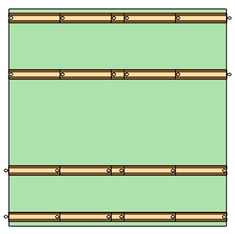
The Square Table
The 36″ depth is also convenient because it is a fairly typical size for a square, folding card table. Two tables placed side-by-side creates a reasonably large layout.
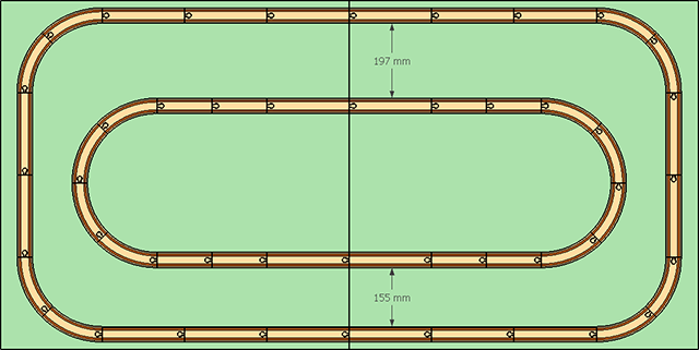
The outer loop is composed of D track, with each half being 3 x D wide and 2 x D tall. The inner loop is composed of A and D track, with each half being 2 x A and 1 x D wide.
These distances are not chosen arbitrarily. From the track equivalencies, two D track can always be turned into three A track, and A track is the basis for the curved switches L and M. Thus the entire layout can be described as being 9 x A wide and 3 x A tall along the outerloop, and 7 x A wide along the inner. The D track can be replaced with N or N1 ascending track, and bridges can be substituted using track math to change D’s to A’s or A1’s as needed to accommodate bridges of various lengths. The D track can also be replaced with T switches, and the track is oriented such that T switches point inward without requiring gender changes.
The distances between loops are also not arbitrary, and I don’t expect people to get out a ruler to measure out the gaps. These measurements come from the track configurations which connect the inner and outer loops, and these will help you lay them out.
The front connection is an A1 track in between two curved switches: L-A1-M. The rear connection is more complex, with two E track between curved switches: L-E-E-M. This connection is not quite a perfect fit, but is so close that the gap is really only noticeable in precise CAD drawings. Note that the straight track on both the inner and outler loops has to be adjusted to account for the switch track, in some cases exchanging 3 x A for 2 x D, and in others reordering D and A.
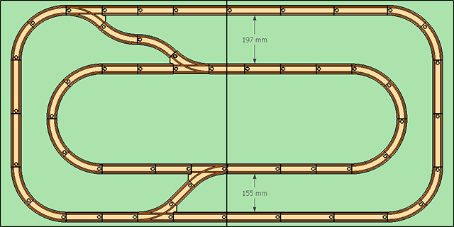
The rear connection may seem odd, but it is actually quite flexible. The E track can be replaced with switches L or M, creating a third line that can connect to either the inner or outer loop. This can be used to create a siding, or even a yard configuration with a buffer stop at the end.
The front connector can also create a new line or siding by exchanging switches O1 or P1 for the A1 track. This track can easily connect ot the outer loop using E1-L or E1-M, but connections to the inner loop are only possible using O1 or P1 which forces a join to the outer loop as well.
Card Table Expansion
Adding tables in the middle is the easiest way to expand the layout. Each 3′ square section uses 4 x D and a single A2 track to lengthen the loops. This track configuration is a little bit larger than the base table by about 4 mm, so it will gradually push the loop turnarounds towards the edges of the play area as you expand, but there is enough clearance there already that it would take 20 tables before you ran out of space (and this could be compensated for by removing an A2 track from the middle, even if a 20+ table layout was feasible).
Full-Width Plywood Sheets
If you are working on a full-width 8’x3′ plywood sheet instead of 36″ square card tables, you have quite a bit more space for your layout.
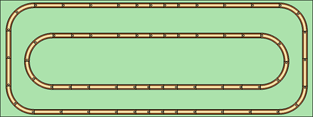
The outer loop is formed bye 6xD, 2xA, and 3xA1, while the inner loop is 2xD, 6xA, and 3xA1. This geometry is a bit more complicated, mostly because the 8′ width really means you have two 4′ halves.
If you have lots of space to work with, then you can turn each plywood sheet into its own half-loop.
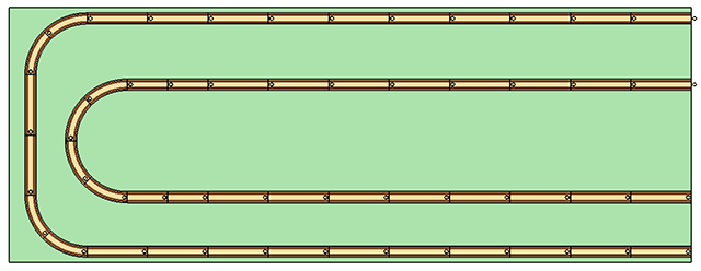
Here, the outer loop is 10xD, and the inner is 2xA and 8xD.
But Loops are Boring
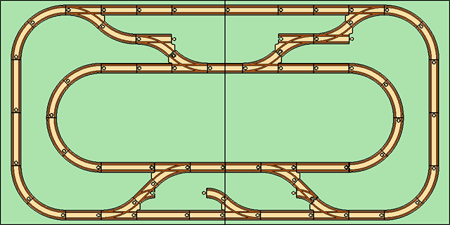
Think of loops as the starting point. The configurations shown here enable a number of switch track options that lead to more complicated and visually interesting layouts. The point of the loops is to start from a position of success—namely, frustration-free switching options because they are guaranteed to join—and go from there. You can shorten the inner loop, substitute curves for straights, turn long straight runs into bridges, and much more.
That being siad, it’s the accessories that make layouts interesting. The more track you lay down, and the more dense the configuration, the less room there is for scenery.
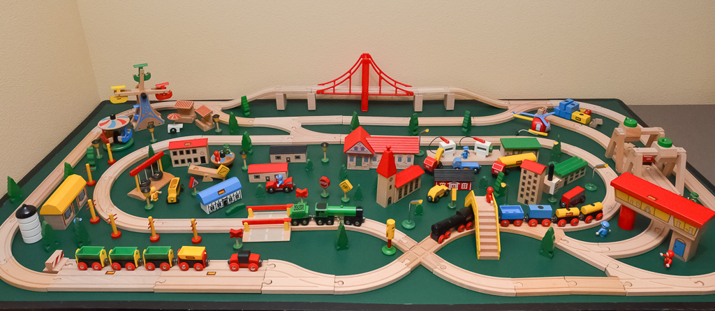
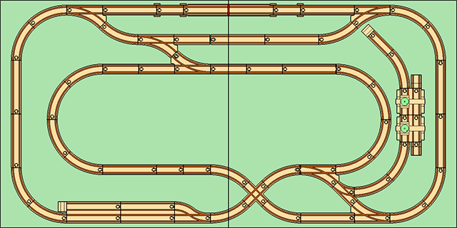
This two-square-table layout was made using a few simple changes to the basic loops. It has a short bridge span, a freight terminal, two sidings, and even a cross track. It was trivial to put together, and was assembled in less than 30 minutes.