Yards: Coach Yards

Coach yards are rail yards that house passenger trains, whether they be traditional gauge or light rail. These are typically through yards but stub yard configurations exist as well.

Coach yards tend to be very dense, so modeling a coach yard in the BRIO railway system means putting track as close togehter as possible. Make use of O1, P1, F1, G1, and even F2 and G2 if you have them. You’ll also need to make sure that your shortest span is long enough to accommodate your passenger trains. Because of this length requirement, coach yards tend to take up a great deal of space.

This following yard configuration makes use of the Maxim 3″ Mini Straights.

Some coach yards provide more than just coach storage, and include maintenance yards, engine storage and other features. The following coach yard is loosely modeled after a light rail coach yard and maintenance facility in the Portland, OR metropolitan area. A station platform lies along a siding off the main branch, and the coach yard wraps around it. This yard is quite large and includes both the Fix-It Shed and Engine Shed, but is still small enough to fit within the confines of the basic loops and also leave space for additional accessories or sidings.

Yards: Freight Yards

As the name implies, a freight yard is where cargo is loaded onto, and unloaded from, rolling stock. In the real world, a freight yard is a complex entity consisting of cranes, marshalling/classification yards, goods stations, container storage, and so on. While many of these elements can be modeled in the BRIO universe, some simplification is necessary at the very least so that the layout will fit in a reasonable amount of space.

Yard Configuration

The first consideration is whether to model the freight yard as a stub yard or a through yard, as the yard configuration and the loading equipment are heavily intertwined.

Stationary Equipment: Through Yards

If the loading equipment is fixed then it is up to the train to move so that each car can be loaded or unloaded, and the yard should be modeled as a through yard. Stationary equipment would include accessories such as:

  • 3324 / 31405-37 Hopper
  • 33242 Tower Crane
  • 33244 Sliding Container Crane
  • 33245 Low Level Crane
  • 33324 Push and Load Tower
  • 33325 Dockside Crane Depot/Loading Dock and Crane
  • 33327 Crane
  • 33380 Harbour Crane
  • 33386 Overhead Crane
  • 33552 Fuel Tank Station
  • 33554 Crane and Funnel Load

Because of the size of many of these accessories, some of which have a large footprint and even an integrated base, the through yard will need to make sufficient space for both the equipment and any supporting vehicles. There are several options for incorporating a freight yard into a design based on the basic loops.

One approach is to simply make the inner loop into the freight yard. This works well for smaller layouts, such as those based on two 36″ card tables. The inner loop can be shortened in order to make more room for non-industrial accessories such as a town.

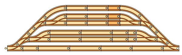
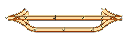
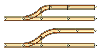
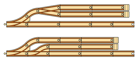
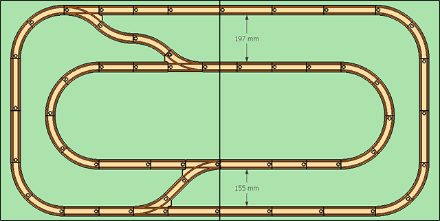
A second approach is to place the freight yard at one end of the outer loop.

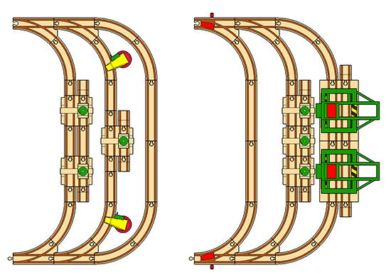
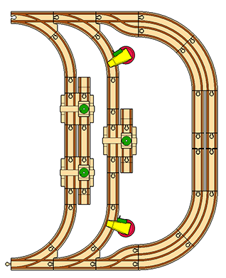
In the left configuration, the main line is the outer-most track and the yard is comprised of the two short circuits. It’s show here with three #33386 Overhead Cranes and two #33327 Cranes as the yard elements with plenty of space left for vehicles to enter and exit.

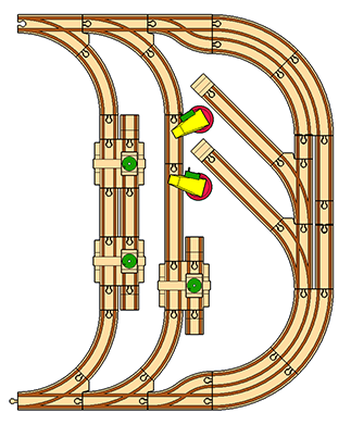
In the right configuration, the shorter route is actually the main line and the outer branches are the freight yard. Trains should not enter into yards by default, so use the mechanical switches L1 and M1 to force the them to follow the curved path without requiring any special handling. This configuration is well suited to modeling shipyards. Shown here are three #33386 Overhead Cranes, and two #33244 Sliding Container Cranes.

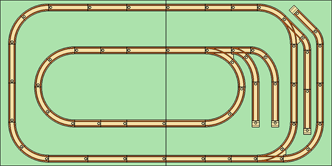
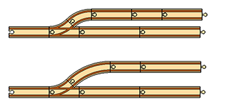
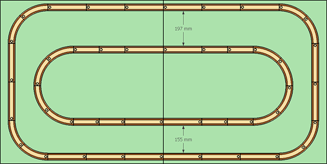
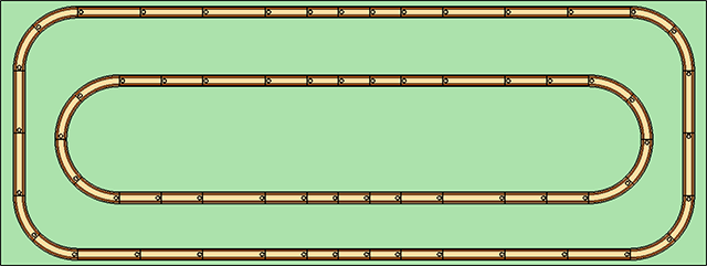
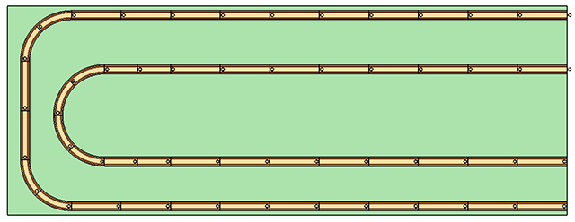
A third approach for the freight yard is to create a dedicated loop near one end of your outer loop.

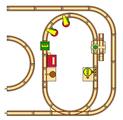
You’ll need to shorten your inner loop to make room for this “end loop”, of course. This special loop becomes its own self-contained freight yard that does not interfere with the rest of your layout, and is well suited to holding numerous accessories with unusual footprints. If needed, you can use gender changers to orient accessories such that their bulky structures are on the loop’s interior. Shown above are the #33667 Water Tower, #33324 Push and Load Tower, #3324 Hopper, two #33327 Cranes, #33386 Overhead Crane, and #33552 Fuel Tank Station.

Moving Equipment: Stub Yards or Through Yards

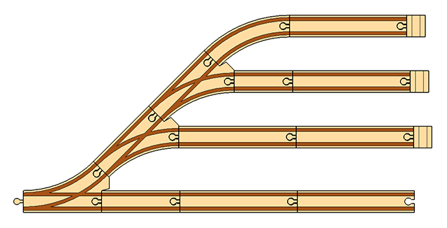
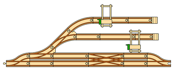
If the loading equipment can move, then the train does not have to and either a stub yard or a through yard configuration will work. Moving equipment typically implies a rolling gantry crane, such as the vintage #33323 or the more recent #33732, but any rolling vehicle with a crane can serve this purpose. And even one or more fixed cranes can service a stub yard if they can cover enough cars.

The resulting stub yard can serve a dual role as both a classification yard and freight terminal.

Receiving Yards

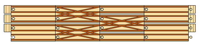
No matter which yard configuration you have chosen, you might want to consider adding a receiving yard. As a reminder, receiving yards are where arriving trains are broken down by switching engines, and departing trains are similarly assembled. A receiving yard is basically a siding connected to the main line at both ends, and are most easily constructed using parallel or straight switches (F, F1, F2, G, G1 and G2) since they keep the main line and the siding synchronized in length.

In the simplified world of BRIO, receiving yards probably make the most sense in a stub-type freight yard, but they can work for either configuration.

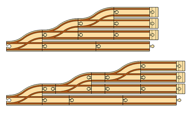
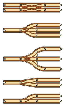
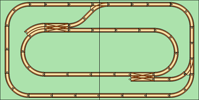
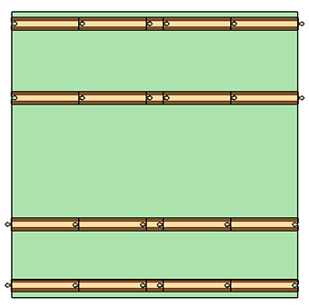
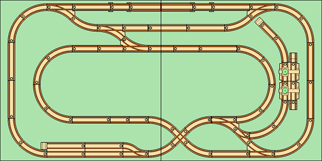
Here, we have a stub yard with two freight terminals and a receiving yard implemented using F2 and G2, with a K switching and crossing track thrown in.

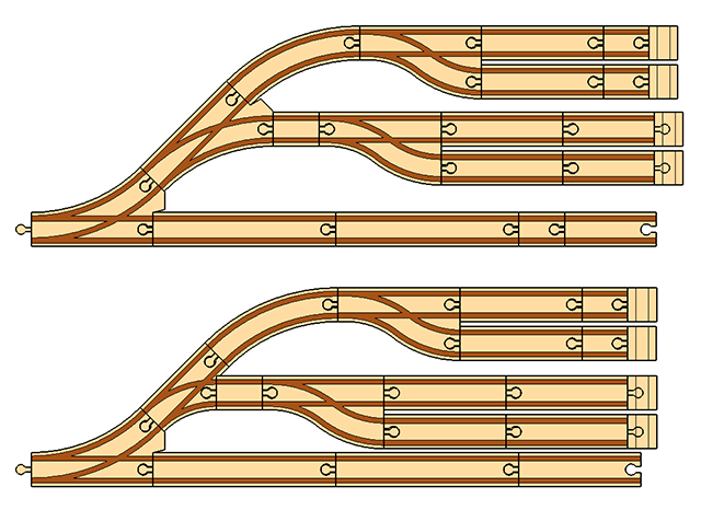
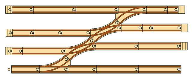
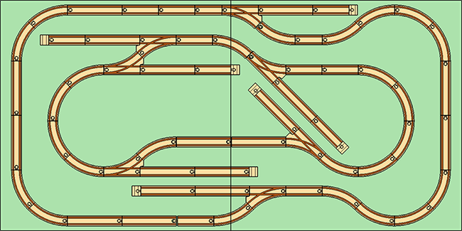
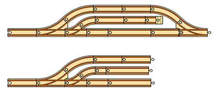
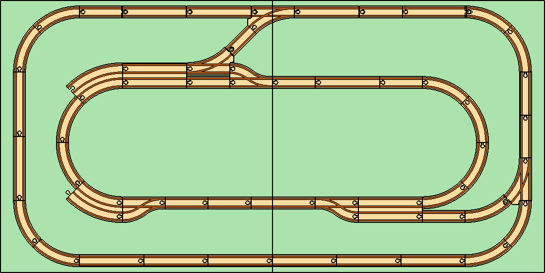
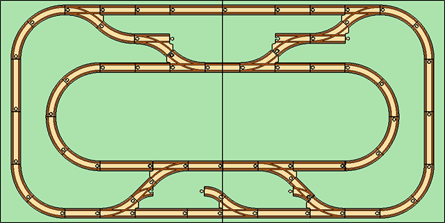
Implementing an arrival yard into a through yard is not much different, though doing so in a yard placed at the ends of the outer loop is a job for double curved track.

The space in the middle can be used for buildings or other accessories, or it can be filled with track to form a more complex yard with multiple elements.

This configuration includes freight terminals, a classification yard and a receiving yard, and still leaves some space for buildings and other accessories.

Putting it all together

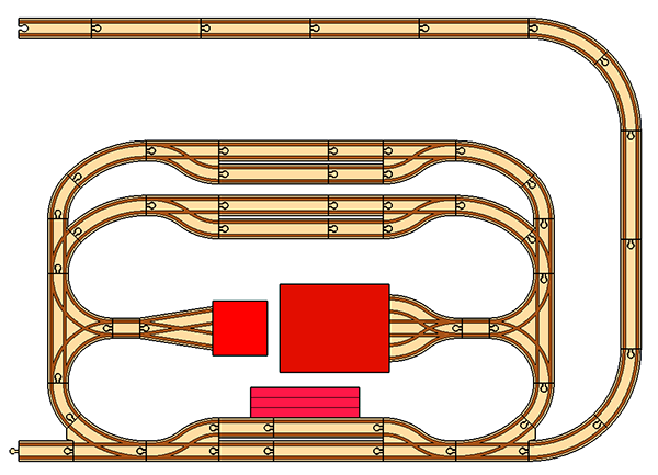
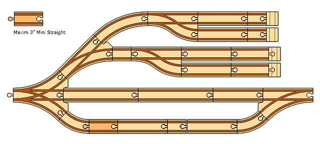
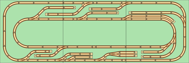
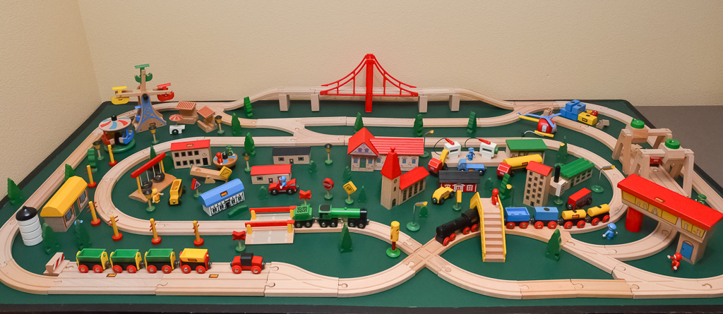
Here’s a full layout, made on an 8′ x 3′ table, that models one large freight yard, and a smaller ship yard. The main freight yard has a classification yard, engine shed to house a switching engine or two, a receiving yard, and a through yard with overhead cranes and a hopper. A roudhouse provides storage for engines. At the other end is a small shipyard, also modeled as a through yard with a sliding container crane for loading and unloading barges and container ships.
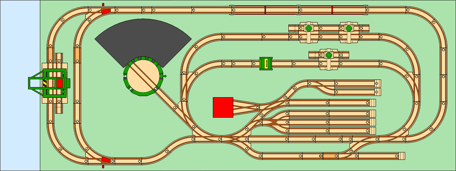
(Click to enlarge.)

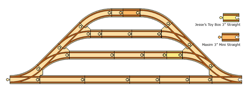
This layout does not make use of the basic loops because of the yard size and complexity, and involves a number of specialty pieces including some of the Maxim 3″ straights.

Yards: Alternative Constructs

The basic stub and through yard is constructed from a series of large or short curved switches, but they aren’t your only options. If you have some specialty track pieces, you can produce yard layouts that increase the track density, stretch out the yard to make it thinner and longer, or just give you a completely different, albeit less realistic, look.

The Parallel Switch

A natural choice for a yard is to use the parallel switch. Not only can you build very dense track layouts, but you can keep all of the branches even with one another. This approach can produuces a very skinny yard, which may be easier to fit into a layout and is, in fact, a bit more like a real yard. The down sides are that it can take a lot of parallel switches to pull off, and you get a wavy track instead of a nice, straight line.

The first form uses three of the same switch to create the most compact layout. This can easily be reversed on the other side to createa through yard. The second form uses gender changers to alternate beween the F1 and G1 switch in a stub yard. This is merely a technique for not using so many of the same switch type in one area, if that’s a concern.

The basic yard configuration can also be augmented by the parallel switch. This creates a yard that is a balance between overall density and the number of parallel switches.

Again, gender changers are included so that the parallel switches can be alternated between F1 and G1.

Cross Track

Cross track K1 can form a long and skinny switch yard. While this doesn’t really model a realistic layout, it is a reasonable stylization and is visually appealing. Cross track forms the basis of #33303, the Shunting Yard Epxansion Pack, and #33230, the vintage Container Terminal. Because this method is based on D and K1, however, it requires quite a bit of length.

The Curved Crossing

Sold as part of #33307, the Advanced Expansion Pack, the curved crossing track H3 is intended for joining two circles but it can also be used to form two stub yards from a single spine.

The Double Curved Switch

With a branch in either direction, the double curved switches I and J are ideal for creating yard elements on both sides of the main line. One branch can be used for a stub configuration such as a classification yard, and the other for a through configuration such as an arrival or departure yard.

Here, a Maxim 3″ Mini Straight is used to make a clean fit.

Yards: An Introduction

A rail yard is a network of tracks for storing, sorting, loading, and unloading rolling stock and locomotives. One of the most distinguishing features of a rail yard is long stretches of parallel track used to store rolling stock off of the main line. Specially designed locomotives, called switching or shunting engines, are used to move cars around and attach and detach them from trains. These engines are optimized for the job of getting individual cars moving and stopped quickly.

A yard typically has several of the following components:

  • Receiving yard, where incoming trains are disassembled. Sometimes called an arrival yard.
  • Departure yard, where cars are assembled into trains.
  • Switching yard, where rolling stock is organized and stored. In the U.S. and some parts of Canada, these are called a classification yard, and in the U.K. and some parts of Canada, they are called a marshalling yard. The term shunting yard is less common.
  • Freight terminal, for loading and unloading rolling stock.
  • Engine house or roundhouse, where locomotives are stored, fueled, and serviced.
  • Maintenance yard, where rolling stock is serviced.

Yard components can also be described by their geometry. A stub yard is a yard layout with an egress on only one end, which a typical configuration for a switching yard. In contrast, a through yard connects on both ends. This is a common configuration for receiving and departure yards, but it is also used in switching yards as well.

What you’ll need

Because yards have so many elements even a simple configuration can take up a great deal of space. Indeed, one could very easily fill an entire table with just a classification yard, and consume a half a dozen L and M switches in the process. Add a roundhouse, turntable, engine shed, and other accessories, and one could conceivable build an entire two or three table layout that was nothing more than a yard! So obviously some simplification and compaction is necessary, particularly if you are limited in space, track, or both.

That being said, even a simple yard is going to take a lot of track, and in particular a lot of switches. This is the one place where I recommend you have specialty pieces, and possibly some third party track to help you along. Here’s what should be in your toy box:

  • L and M switches, and lots of them. You can easily use a half dozen switches in a yard, and what can be particularly frustrating is that you won’t use them in equal amounts. You might need six of one, and one or two of the other.
  • O1 and P1 switches. I am not a huge fan of the tighter E1 curves for several reasons, but making a classification yard, or even a siding for a departure and receiving yard, is going to take a lot of space if you are using L and M. If you don’t have a lot of room, these are your only option. It is unfortunate that the genuine BRIO switches can be hard to come by outside of #33307, the Advanced Expansion Pack.
  • The T Switch, which will allow your locomotive to turn around.
  • A turntable, for the same reason. Note that the Mechanical Turntable, #33361, is too small for the large and medium-sized engines, so you should consider one of the larger, retired turntables such as #33460 the Round Turntable, or #33276 the Grand Turntable.
  • At least one pair of F1 and G1 parallel switches. These are the most compact means of building a siding.
  • U and V ramp tracks
  • R and S buffer stops
  • At least one pair of I and J double curve switches. These are space-savers, allowing you to use one switch in place of two L or M laid end-to-end.
  • Some sort of A3 track equivalent. If you can find genuine A3 track, then great! Otherwise, consider the 3″ straights from either Maxim or Jesse’s Toy Box as a substitute. You’ll need them for through yard configurations.
  • A round house, engine shed, or both.

Stub Yards

Some common constructions for a stub yard using BRIO track are below.

This is the most basic configuration, using three curved switches (in this case, 3 x M) to form three spurs. Keeping all of the branches to an identical length is not really possible, something that will become a problem later on when we discuss through yards.

An alternative arrangement is to split the middle branch into two branches. This does not change the total area needed by the yard, but it does alter length and spacing of the first two sidings. This approach of making a branch off of the main artery of the yard and splitting it again is fairly common in real switching yards.

If space is absolutely at a premium, then you can use the short cuved switches O1 and P1, and the short curve E1 to make the yard more compact.

Through yards

The geometry of through yards can be problematic because you have to make multiple sidings split and then rejoin. While the Vario System can generally soak up small differences in track lengths, when you make multiple joints you end up forming a far more rigid structure. Imprecise alignments that can be ignored in typical BRIO layout quickly become huge problems in a through yard, as you can no longer force the track to fit.

The layouts presented so far have all used genuine BRIO track, but when it comes to through yards the use of third party track simply cannot be avoided. Even if you are fortunate enough to possess some of the rare A3 pieces, the slightly longer Jesse’s Toy Box 3″ straight, and longer still Maxim 3″ straight, are necessary components.

Another problem with through yards is simply the space required. If you want more than one or two sidings, you are going to need a lot of room.

Changing from L and M switches to O1 and P1 switches does compact the layout.

BRIO created a simpler, smaller version of a through yard in its vintage sets, such as this configuration from the 1987 starter set #33143. It uses Ex2 + Dx2 in the siding, and A + Dx2 in the main line.


Sidings: In the Basic Loops

You can easily incorporate sidings into the basic loops, and you have three basic options.

In between loops

The first option is to place them within the space between the inner and outer loops. The image below shows the large number of siding configurations that can be achieved, and this is just a start. Of course, this would not be an actual layout since the two loops do not connect. The point here is to show what configurations are possible, and where.

Having nested sidings in between the two loops maximizes the use of the space by increasing the track density. An individual siding is much longer than it is deep, so nesting and layering can make use of what would otherwise be wasted space. These formations also result in a more visually interesting layout.

At loop ends

By shortening the loops on either side you can make room for sidings outside the loop ends, some of which can be quite lengthy. This technique is a good starting point for building yards.

At turns

Anywhere you place an E you can potentially use an L or an M to build a siding that branches straight from the main line. The same goes for E1, which can potentially be replaced with O, O1, P, or P1. By breaking up long runs of straight track with curves you create additional siding options, and more exciting railways.

Sidings: Building blocks

A siding is a short spurs off of the main rail line that both allows other trains on the same line to pass, and provides temporary storage for rolling stock. Just a few sidings in a BRIO layout can add a great deal of visiual interest. They are easy to create using the standard track pieces that are common in BRIO starter sets, expansion sets, and individual track packs. Fairly intricate and elegant arrangements are possible without having to resort to exotic or retired track.

The basic siding is created with a combination of E, E1, and L or M:

If you have O1 or P1 track, you have the following options:

Note that the track spacing of the O1/P1-E configuration is the same as the L/M-E1 configuration. Use of O1/P1 and E1 makes for an even denser layout.

These configurations can be mixed and matched to build fairly intricate and complex track configurations, such as nested sidings and even branches that reconnect with the main line on the other end. One of the primary motivations for keeping sidings aligned with the main line is to allow for these double-ended connections.

If you own some of the more exotic (and retired) switches, you get additional siding options:

The advantage of the parallel and straight switches is that they enable the use of double track, and of course keep both the main line and the spur perfectly even with one another. The F1 and G1 switches, in particular, are a natural choice. I am not a huge fan of using the straight switches F and G by themselves, however, since they introduce an offset in the main line and force the train to navigate a switch.

Again, mixing and matching can greatly expand your layout options, and provide fairly dense track configurations.

The best way to terminate a siding is with a buffer stop, though if you do not have enough buffer stops then a ramp track is cleaner than an open connector.

Later, I’ll discuss incorporating sidings between the basic loops, and then expand to building yards.

Loops with Double Track

The basic loops can also be connected using double track. If you have one or more of the switching and crossing track, type K, then you can make the following joins.

The upper join uses L/M-A1-E-K and the lower join comes from one of the loop sides using L/M-E-A-K. Neither are perfect fits. These constructs also enable the use of double curves along in the inner loop.

Joins without track type K are also possible if you use parallel switches F1 and G1. These track types are less common, however.

I am showing K1 track for simplicity, but this is equivalent to a pair of D track if that’s all you have. This type of join is less flexible because it has a more complicated track geometry.

The Basic Loops

A good starting point for BRIO layouts is a symmetrical loop around the perimeter of the table. The loop constructed in this fashion gives you two long runs of straight track, making it possible to incorporate large bridges and ascending track into the layout while still providing ample depth for large curves at the ends. The symmetrical layout also makes it easy to add curves or switches into one side: as long as you apply the same, or an equivalent, change to the other side, your loop will still connect. A second loop, nested inside the first one, provides additional layout options by adding a secondary line which can switch and cross with the main line. The center of the loops, as well as the space between them, provide ample space for accessories and scenery.

I like to plan layouts around a 36″ depth, as mentioned in the discussion on train tables. This provides enough space for creative track layouts using E track and its derivatives while staying shallow enough to enable reaching across the table.

The Square Table

The 36″ depth is also convenient because it is a fairly typical size for a square, folding card table. Two tables placed side-by-side creates a reasonably large layout.

The outer loop is composed of D track, with each half being 3 x D wide and 2 x D tall. The inner loop is composed of A and D track, with each half being 2 x A and 1 x D wide.

These distances are not chosen arbitrarily. From the track equivalencies, two D track can always be turned into three A track, and A track is the basis for the curved switches L and M. Thus the entire layout can be described as being 9 x A wide and 3 x A tall along the outerloop, and 7 x A wide along the inner. The D track can be replaced with N or N1 ascending track, and bridges can be substituted using track math to change D’s to A’s or A1’s as needed to accommodate bridges of various lengths. The D track can also be replaced with T switches, and the track is oriented such that T switches point inward without requiring gender changes.

The distances between loops are also not arbitrary, and I don’t expect people to get out a ruler to measure out the gaps. These measurements come from the track configurations which connect the inner and outer loops, and these will help you lay them out.

The front connection is an A1 track in between two curved switches: L-A1-M. The rear connection is more complex, with two E track between curved switches: L-E-E-M. This connection is not quite a perfect fit, but is so close that the gap is really only noticeable in precise CAD drawings. Note that the straight track on both the inner and outler loops has to be adjusted to account for the switch track, in some cases exchanging 3 x A for 2 x D, and in others reordering D and A.

The rear connection may seem odd, but it is actually quite flexible. The E track can be replaced with switches L or M, creating a third line that can connect to either the inner or outer loop. This can be used to create a siding, or even a yard configuration with a buffer stop at the end.

The front connector can also create a new line or siding by exchanging switches O1 or P1 for the A1 track. This track can easily connect ot the outer loop using E1-L or E1-M, but connections to the inner loop are only possible using O1 or P1 which forces a join to the outer loop as well.

Card Table Expansion

Adding tables in the middle is the easiest way to expand the layout. Each 3′ square section uses 4 x D and a single A2 track to lengthen the loops. This track configuration is a little bit larger than the base table by about 4 mm, so it will gradually push the loop turnarounds towards the edges of the play area as you expand, but there is enough clearance there already that it would take 20 tables before you ran out of space (and this could be compensated for by removing an A2 track from the middle, even if a 20+ table layout was feasible).

Full-Width Plywood Sheets

If you are working on a full-width 8’x3′ plywood sheet instead of 36″ square card tables, you have quite a bit more space for your layout.

The outer loop is formed bye 6xD, 2xA, and 3xA1, while the inner loop is 2xD, 6xA, and 3xA1. This geometry is a bit more complicated, mostly because the 8′ width really means you have two 4′ halves.

If you have lots of space to work with, then you can turn each plywood sheet into its own half-loop.

Here, the outer loop is 10xD, and the inner is 2xA and 8xD.

But Loops are Boring

Think of loops as the starting point. The configurations shown here enable a number of switch track options that lead to more complicated and visually interesting layouts. The point of the loops is to start from a position of success—namely, frustration-free switching options because they are guaranteed to join—and go from there. You can shorten the inner loop, substitute curves for straights, turn long straight runs into bridges, and much more.

That being siad, it’s the accessories that make layouts interesting. The more track you lay down, and the more dense the configuration, the less room there is for scenery.

This two-square-table layout was made using a few simple changes to the basic loops. It has a short bridge span, a freight terminal, two sidings, and even a cross track. It was trivial to put together, and was assembled in less than 30 minutes.